Jul 14, 2026
Fine Powder Screening Guide
Why Fine Powders Blind Test Sieves—and How an Ultrasonic Test Sieve Shaker Helps
Sieve analysis looks straightforward when a material is dry, free-flowing and substantially smaller than the selected openings. The procedure becomes much less predictable when the sample contains fine, cohesive or electrostatic particles. Instead of presenting themselves individually to the mesh, particles form agglomerates, adhere to the wires and progressively cover usable openings. The operator may extend the test, increase mechanical vibration or stop repeatedly to brush the mesh, yet the result can remain slow and difficult to reproduce.
An ultrasonic test sieve shaker addresses this specific limitation by combining conventional laboratory sieve motion with high-frequency energy applied to one dedicated sieve frame. The mechanical shaker continues to move the full sieve stack, while the ultrasonic generator, matched transducer and connected frame target the layer where mesh blinding is most likely to occur. The goal is not to replace a sound test method or guarantee a clog-free result. It is to keep more of the critical mesh area active and make difficult fine-powder screening easier to control.
In This Guide
Why fine powders blind sieve mesh
Where mechanical screening reaches its limit
How ultrasonic-assisted sieving works
What changes in the screening process
Applications in research and advanced materials
How to select a suitable system
Method-development recommendations
Test-sieve standards and result comparability
Frequently asked questions
Key Takeaways
Fine powders can blind mesh because cohesion, electrostatic behavior, particle shape and loading can prevent individual particles from reaching open apertures.
Mechanical horizontal and vertical motion remains responsible for moving the complete sieve stack and separating ordinary powders and granules.
Ultrasonic assistance introduces high-frequency vibration directly into one dedicated sieve frame at the most difficult separation point.
The most defensible benefits are reduced blinding, improved dispersion and more consistent screening—not “zero clogging” or guaranteed analytical accuracy.
Method repeatability still depends on representative sampling, verified test sieves, controlled sample mass, documented settings and consistent cleaning.
Why Do Fine Powders Blind Test-Sieve Mesh?
Coarse, free-flowing particles are dominated largely by gravity and collision. Fine powders behave differently because their mass decreases faster than the relative influence of surface forces. Cohesion between particles, electrostatic charging, moisture, irregular morphology and soft agglomeration can therefore become more important than gravity. A nominally fine sample may reach the sieve as clusters rather than as discrete particles.
Mesh blinding occurs when particles lodge in apertures, bridge across openings or build a persistent layer on the wire cloth. Once part of the mesh is covered, the effective screening area shrinks. Material then concentrates on the remaining open area, increasing local loading and making further blockage more likely. This feedback loop explains why a test may start normally and then slow dramatically.
Aperture size alone does not predict the difficulty. Two powders with similar nominal particle-size distributions can behave very differently because of particle shape, surface texture, density, oxidation, humidity or formulation additives. Gas-atomized metal powder may flow differently from water-atomized powder. A dry ceramic powder may behave differently after storage. A pharmaceutical blend may contain a small cohesive fraction that controls the behavior of the whole sample.
Experimental work on vibrated fine-powder beds illustrates this broader point. Studies by Sonar and Katsuragi observed consolidation, fracture and decompaction behavior in cohesive micron-scale powder under different vibration conditions. Their work concerns powder-bed vibration rather than ultrasonic sieving, but it reinforces an important practical lesson: cohesive fine powders do not respond like free-flowing grains, and simply applying “more shaking” does not create one universal outcome. See the authors’ original studies on decompaction-wave propagation and vibration-induced fluidization of fine powder.
Where a Conventional Laboratory Test Sieve Shaker Reaches Its Limit
A well-designed laboratory test sieve shaker is still the foundation of the process. Horizontal forward/reverse rotation distributes material across the sieve surface, while vertical vibration lifts and reorients particles so that they can approach apertures in different orientations. With suitable test time, sample mass and sieve selection, this combined motion is effective for many powders and granules.
The limitation appears when mechanical motion moves the stack but cannot keep the critical fine mesh clear. Increasing time may only circulate an agglomerated layer. Increasing intensity can sometimes compact material against the mesh, accelerate sieve wear or change the balance between passage and retention. Manual brushing interrupts the method and introduces another operator-dependent variable. Adding dispersing aids can alter the sample and may be unacceptable for research, pharmaceutical or high-purity material workflows.
The useful question is therefore not “Is ultrasonic always better?” It is “At which sieve layer does adhesion or blinding prevent the mechanical method from completing its intended separation?” An ultrasonic system is most valuable when that critical layer can be identified and fitted with a dedicated ultrasonic frame.
How Does an Ultrasonic Test Sieve Shaker Work?
An ultrasonic-assisted laboratory system contains two coordinated but distinct sources of motion. Understanding their roles prevents unrealistic expectations and helps the laboratory design a repeatable procedure.
1. The Mechanical Shaker Moves the Entire Stack
The shaker provides the conventional screening action for every installed sieve: horizontal forward/reverse movement plus vertical vibration. It carries the sample across successive apertures and collects size fractions in the appropriate pans. Touchscreen models can store operating programs so laboratories can document and recall speed, intensity, frequency, run count and motion timing for repeated procedures.
2. The Ultrasonic Generator Produces High-Frequency Output
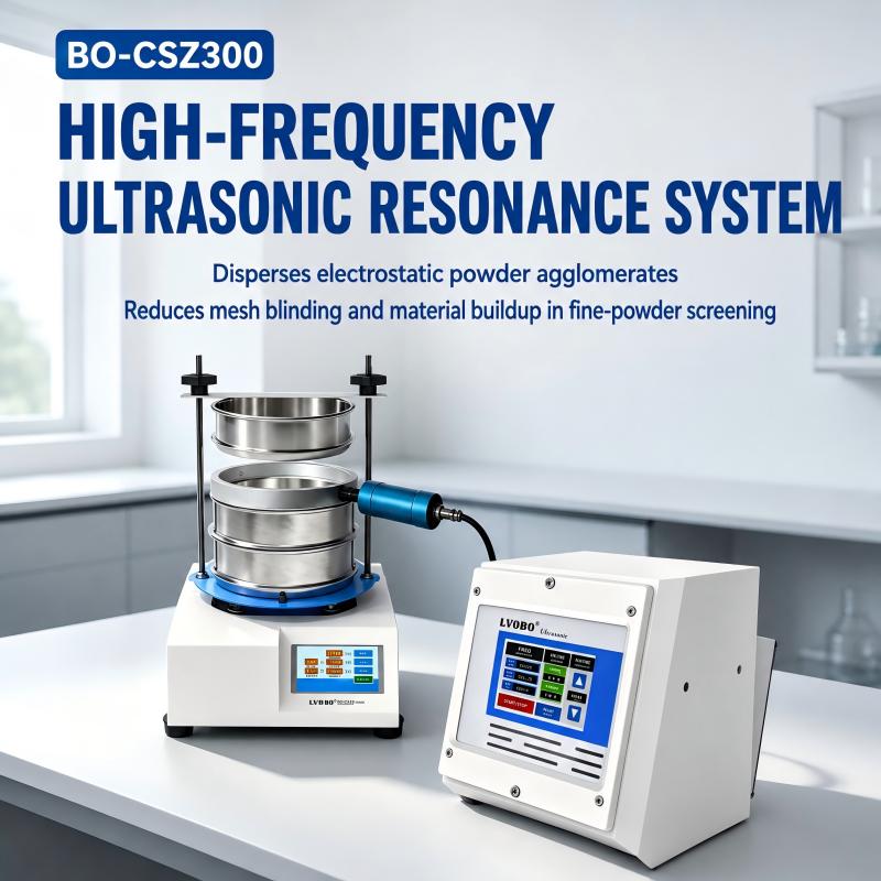
The separate generator produces a controlled high-frequency electrical signal. In the LVBO configuration discussed here, the nominal output frequency is 28 kHz, with adjustable amplitude and a touchscreen display for time, temperature and power information. Frequency is a system specification; it should not be interpreted as a test-sieve standard or a guarantee that every material will respond identically.
3. A Matched Transducer Transfers Energy
The transducer converts the generator’s electrical output into mechanical ultrasonic vibration and transfers that energy through its connection to the dedicated sieve frame. Matching the generator, transducer, connection and frame matters because losses or unstable coupling can reduce the energy that reaches the mesh.
4. One Dedicated Frame Targets the Critical Layer
In this product configuration, ultrasonic energy is applied to one dedicated ultrasonic sieve frame per system. The other sieves still receive the shaker’s mechanical motion. This focused architecture lets the laboratory position ultrasonic assistance at the layer most vulnerable to blinding rather than implying that every sieve in a tall stack is ultrasonically energized.
What Changes When Ultrasonic Assistance Is Added?
More Active Screening Area
High-frequency vibration at the mesh can make it harder for fine particles to remain lodged in openings or attached as a persistent layer. Keeping more apertures active supports continued passage at the critical separation point. The appropriate claim is “reduced mesh blinding,” not “zero clogging,” because performance remains material- and method-dependent.
Improved Dispersion of Soft Agglomerates
Ultrasonic energy can help disturb weakly bound clusters and reduce the residence time of powder on the mesh. That can be useful for electrostatic, low-density or cohesive powders that otherwise travel as lumps. It should not be assumed to deagglomerate every strongly bonded particle or to replace a separate sample-dispersion step when the method requires one.
More Consistent Test Completion
If blinding is the main cause of an incomplete or excessively long test, keeping the selected frame active can reduce operator intervention and make endpoint behavior more consistent. Repeatability still depends on the complete method: sample preparation, sieve condition, loading, operating parameters, duration, environmental control and cleaning.
Better Control Than Simply Increasing Mechanical Intensity
Ultrasonic assistance adds energy where the problem occurs—the selected mesh—without requiring the laboratory to drive the entire stack more aggressively. This can be a more targeted response than extending test time or increasing overall mechanical intensity. The optimum amplitude should be established experimentally for each material rather than automatically set to maximum.
Where Is Ultrasonic-Assisted Sieving Most Useful?
Metal Powders and Additive Manufacturing
Metal powder particle size analysis supports incoming inspection, powder-lot comparison, reclaimed-powder monitoring and research into process consistency. Fine or irregular fractions can adhere to mesh, while high-density particles place significant load on the sieve. An ultrasonic frame can be positioned at the critical cut point to support metal-powder classification. Research on vibratory feeding of gas- and water-atomized metal powders also demonstrates that powder type and operating parameters materially affect flow behavior; see the original additive-manufacturing study by Sinclair and colleagues on vibratory powder feeding.
Battery Materials and New-Material Research
Cathode, anode, conductive and precursor powders may be fine, electrostatic or sensitive to contamination. Research teams often need controlled separation for material preparation, comparative studies or quality checks. Stainless-steel material-contact components and documented cleaning procedures should be evaluated against the chemistry and contamination limits of the specific sample.
Pharmaceutical and Food Powders
Fine excipients, active ingredients, nutraceutical powders and milled food ingredients may bridge or agglomerate. Ultrasonic sieving can support development and quality-control studies, but equipment suitability does not by itself establish GMP compliance, hygienic qualification or product-contact compatibility. Those requirements must be assessed within the buyer’s validated process.
Chemical Materials, Pigments and Mineral Powders
Pigments, catalysts, fillers, coatings, mineral powders and fine chemical intermediates frequently combine small particle size with irregular shape or electrostatic behavior. An ultrasonic screening machine can help laboratories complete difficult sieve cuts with less manual intervention, provided the material is compatible with the sieve, seals, transducer assembly and cleaning method.
Electronic Ceramics and Laboratory Testing
Alumina, zirconia and other electronic-ceramic powders require controlled handling because small fractions can affect forming and sintering behavior. Universities and materials laboratories can use sieve-based classification as one part of a broader characterization workflow, particularly when a physical retained fraction is needed for weighing, microscopy or subsequent testing.
How to Select Fine Powder Sieving Equipment
Selection should begin with the material and method, not with the largest available power value. Ask suppliers to evaluate the target cut size, particle morphology, density, sample mass, expected throughput, electrostatic tendency, moisture sensitivity and cleaning requirements.
Identify the Critical Ultrasonic Layer
Determine which aperture is actually blinding. Because this system uses one dedicated ultrasonic frame, it should be installed at the critical separation point. If several layers experience severe blinding, the method may require sequential tests, a different stack arrangement or a separate evaluation rather than an assumption that one transducer energizes every layer equally.
Choose 200 mm or 300 mm
A 200 mm configuration is compact and appropriate for many research-scale samples. A 300 mm configuration provides greater screen area and may suit larger samples or applications that benefit from lower areal loading. Diameter alone does not determine throughput; powder behavior, aperture, sample mass and acceptable endpoint remain important.
Check Generator and Laboratory Compatibility
Confirmed LVBO ultrasonic generator specifications
Models
BO-CSZ200 / BO-CSZ300
Input voltage
AC100–220V
Input power
350W
Approximate output power
300W
Output frequency
28kHz
Generator dimensions
176 × 176 × 220 mm
Dedicated ultrasonic frames
1 per system
Frame options
200 mm / 300 mm
Confirm local voltage, plug, grounding and laboratory electrical requirements before shipment. US, EU, UK and AU plug preparation may be available, but the laboratory remains responsible for confirming local installation and safety requirements.
A Practical Method-Development Workflow
Define the analytical objective. Specify the fractions or critical aperture, acceptable sample mass and how the retained material will be reported.
Prepare a representative sample. Follow the laboratory’s sampling and conditioning procedure. Do not assume the shaker can correct sampling bias.
Inspect and clean the sieves. Check wire cloth, frame, seals and ultrasonic connection. Damaged or contaminated sieves compromise results regardless of the drive system.
Install the dedicated ultrasonic frame at the critical layer. Confirm that the transducer and cable are correctly secured before energizing the generator.
Begin with conservative settings. Establish suitable mechanical motion, time and ultrasonic amplitude through controlled trials. Maximum intensity is not automatically the best setting.
Document the complete recipe. Record sample mass, sieve stack, environmental conditions, mechanical parameters, ultrasonic amplitude, duration and endpoint criteria.
Assess repeatability. Run replicate tests and compare retained masses, completion time and visible blinding. Optimize one variable at a time.
Create cleaning and inspection intervals. Fine powder can accumulate at joints and mesh edges. Follow the manufacturer’s instructions and the laboratory’s contamination-control procedure.
Safety note: Fine powders may present inhalation, reactivity, electrostatic or combustible-dust hazards. Review the material safety data, grounding, ventilation and dust-control requirements before testing. Do not process combustible or reactive powders unless the complete equipment and facility are approved for that hazard. Follow the operating manual and local laboratory rules.
Test-Sieve Standards and Result Comparability
Ultrasonic assistance cannot compensate for an unverified or damaged sieve. Test-sieve standards address the wire cloth, aperture tolerances, frame construction and inspection methods that underpin sieve-based particle classification.
ASTM E11-24 covers woven-wire test-sieve cloth and test sieves used to classify materials by particle size. ASTM states that the specification includes requirements for sieve cloth, test-sieve construction and inspection procedures, with nominal apertures from 125 mm down to 20 µm. ISO 3310-1:2016 specifies technical requirements and test methods for test sieves of metal wire cloth over the same nominal aperture range and remains current after confirmation in 2022.
These standards do not certify that an ultrasonic shaker will produce a particular result for every powder. They establish requirements for the sieve itself. Buyers should therefore phrase procurement requirements carefully: matching sieve pans can be configured to the requested ASTM E11 or ISO 3310-1 specification, while the screening method must still be developed and verified for the material.
Is an Ultrasonic Sieve Shaker a Particle Size Analyzer?
It is more accurate to describe the system as sieve-based particle size analysis equipment. The instrument separates material physically through specified apertures, allowing the laboratory to weigh retained fractions. A laser-diffraction or image-based particle size analyzer uses a different measurement principle and may report an equivalent diameter rather than a physical sieve fraction.
The methods can be complementary. A particle size analyzer can provide rapid distribution data, while a laboratory vibratory sieve shaker can prepare fractions, remove oversize contamination or provide material retained at a defined aperture for further examination. Results from different principles should not be treated as interchangeable without a correlation study.
LVBO’s Combined Mechanical and Ultrasonic Screening System
LVBO combines BO-200SY or BO-300SY touchscreen laboratory shakers with BO-CSZ200 or BO-CSZ300 ultrasonic generators and one matching 200 mm or 300 mm dedicated frame. The shaker supplies programmable horizontal and vertical screening motion for the complete stack. The separate 28 kHz system adds adjustable ultrasonic assistance at the critical fine-powder layer.
This architecture is intended for laboratories that need ordinary sieve separation and targeted anti-blinding assistance in one workflow. Before selection, share the material, target aperture, sample mass, current problem and destination voltage. A supplier evaluation or material trial is more useful than relying only on a generic mesh-number claim.
Frequently Asked Questions
What is an ultrasonic test sieve shaker?
It is a laboratory sieve shaker combined with an ultrasonic generator, matched transducer and dedicated sieve frame. Mechanical motion moves the sieve stack, while high-frequency energy assists the selected mesh layer.
Does ultrasonic screening completely eliminate mesh blinding?
No universal system can guarantee zero blinding for every powder. Ultrasonic assistance is designed to reduce persistent adhesion and blockage. Performance depends on material behavior, aperture, loading, amplitude and test method.
Can one ultrasonic generator energize every sieve in the stack?
In the configuration described here, one dedicated ultrasonic frame is connected per system. The mechanical shaker moves the entire stack, but ultrasonic energy is focused on the selected frame.
Why use 28 kHz?
28 kHz is the nominal output frequency of this matched LVBO generator and transducer system. It identifies the equipment configuration; it is not a test-sieve standard or a guarantee of identical performance for all materials.
Should I choose a 200 mm or 300 mm sieve?
Choose according to sample mass, available bench space, required screen area and existing laboratory method. A 300 mm frame offers more area, while a 200 mm system is more compact.
Which powders are suitable?
Typical candidates include cohesive or electrostatic metal, battery, ceramic, pharmaceutical, food, chemical, pigment and mineral powders. Compatibility and safety must be reviewed for the specific sample.
Can ultrasonic sieving replace a laser particle size analyzer?
Not directly. Sieve analysis produces physical mass fractions based on aperture passage. Laser diffraction uses an optical model. The methods can complement each other but measure particle size differently.
What information should I send when requesting a recommendation?
Provide the material name, target aperture or sieve standard, approximate particle-size range, sample mass, current blinding problem, desired frame diameter, destination voltage and any contamination or safety constraints.
Need to Evaluate a Difficult Powder?
Send LVBO your material, target sieve aperture, sample mass, existing test method and the type of blinding you observe. We can help you compare 200 mm and 300 mm configurations and identify the most appropriate layer for one dedicated ultrasonic frame.
Request a material and configuration review before ordering.
Technical References
ASTM E11-24: Standard Specification for Woven Wire Test Sieve Cloth and Test Sieves.
ISO 3310-1:2016: Test sieves—Technical requirements and testing—Part 1: Test sieves of metal wire cloth.
Sonar, P. and Katsuragi, H. Decompaction-wave propagation in a vibrated fine powder bed.
Sonar, P. and Katsuragi, H. Fracturing-induced fluidization of vibrated fine-powder column.
Sinclair, C. W. et al. Vibratory Powder Feeding for Powder Bed Additive Manufacturing Using Water- and Gas-Atomized Metal Powders.
{
"@context": "https://schema.org",
"@type": "FAQPage",
"mainEntity": [
{
"@type": "Question",
"name": "What is an ultrasonic test sieve shaker?",
"acceptedAnswer": {"@type": "Answer", "text": "It is a laboratory sieve shaker combined with an ultrasonic generator, matched transducer and dedicated sieve frame. Mechanical motion moves the sieve stack, while high-frequency energy assists the selected mesh layer."}
},
{
"@type": "Question",
"name": "Does ultrasonic screening completely eliminate mesh blinding?",
"acceptedAnswer": {"@type": "Answer", "text": "No universal system can guarantee zero blinding. Ultrasonic assistance is designed to reduce persistent adhesion and blockage, with performance depending on the material and method."}
},
{
"@type": "Question",
"name": "Can one ultrasonic generator energize every sieve in the stack?",
"acceptedAnswer": {"@type": "Answer", "text": "In this configuration, one dedicated ultrasonic frame is connected per system. Mechanical motion acts on the entire sieve stack."}
},
{
"@type": "Question",
"name": "Why use 28 kHz?",
"acceptedAnswer": {"@type": "Answer", "text": "28 kHz is the nominal output frequency of the matched LVBO generator and transducer configuration. It is not a test-sieve standard or a universal performance guarantee."}
},
{
"@type": "Question",
"name": "Should I choose a 200 mm or 300 mm sieve?",
"acceptedAnswer": {"@type": "Answer", "text": "Choose according to sample mass, bench space, required screen area and the established laboratory method."}
},
{
"@type": "Question",
"name": "Which powders are suitable?",
"acceptedAnswer": {"@type": "Answer", "text": "Typical candidates include cohesive or electrostatic metal, battery, ceramic, pharmaceutical, food, chemical, pigment and mineral powders, subject to compatibility and safety review."}
},
{
"@type": "Question",
"name": "Can ultrasonic sieving replace a laser particle size analyzer?",
"acceptedAnswer": {"@type": "Answer", "text": "Not directly. Sieve analysis produces physical mass fractions based on aperture passage, while laser diffraction uses an optical measurement model."}
},
{
"@type": "Question",
"name": "What information should I send when requesting a recommendation?",
"acceptedAnswer": {"@type": "Answer", "text": "Provide the material, target aperture, particle-size range, sample mass, current blinding problem, frame diameter, destination voltage and safety constraints."}
}
]
}
Read More
 English
 English
 Español
 Tiếng Việt


 3rd Floor, Building 8, Licheng Science and Technology Innovation Center, No. 188 Taixin Street, Licheng District, Quanzhou City, Fujian Province, China
 Tel : +86 -13788824251
 Email : lvobo2026@gmail.com,Ivobo2088@gmail.com
 WhatsApp : +86 -13788824251


 IPv6 Network Supported