Oct 23, 2026
Fine powder screening can become difficult when particles accumulate on sieve openings, restrict material flow, or form agglomerates during separation. These problems may increase screening time, require frequent mesh cleaning, and affect the consistency of particle classification.
An ultrasonic sieve deblinding system can help address these challenges by introducing high-frequency vibration to the screening mesh.
However, selecting the right system involves more than comparing frequency and power ratings. Sieve diameter, component matching, mesh specifications, equipment compatibility, and operating conditions all influence screening performance.
This practical guide explains how ultrasonic deblinding works, how to choose between 200mm and 300mm sieve configurations, which technical specifications matter, and how to evaluate performance before purchasing.
1. What Is an Ultrasonic Sieve Deblinding System?
An ultrasonic sieve deblinding system is designed to reduce mesh blockage during fine powder screening.
It introduces high-frequency vibration to the screening mesh, helping prevent particles from accumulating in sieve openings and maintaining more effective screening conditions.
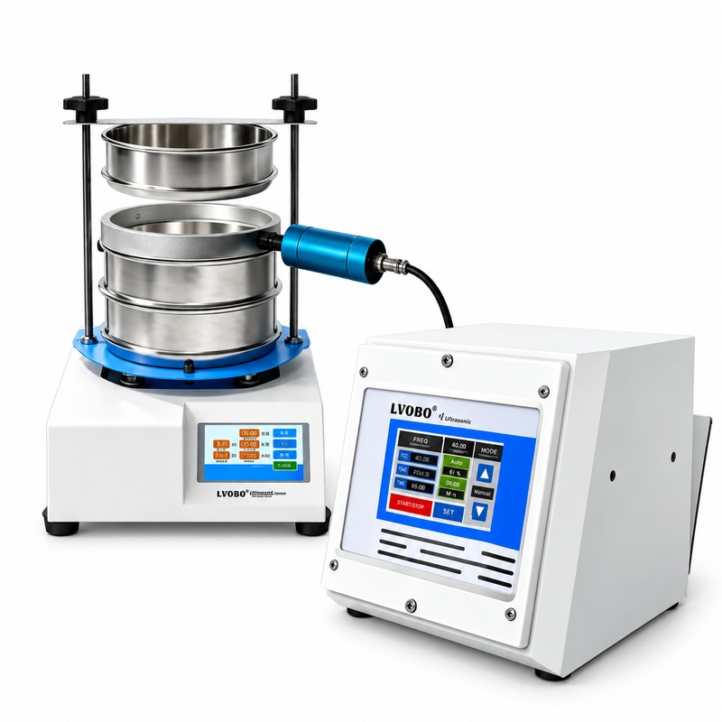
A typical ultrasonic system consists of three main components:
Ultrasonic Generator
Produces the high-frequency electrical signal required to operate the ultrasonic screening system.
Ultrasonic Transducer
Converts the electrical signal into high-frequency mechanical vibration.
Ultrasonic Sieve Frame
Transfers ultrasonic vibration to the screening mesh and provides a suitable mounting structure.
These components function together as a matched system.
Importantly, ultrasonic deblinding is generally used alongside a compatible mechanical sieve shaker. The mechanical equipment provides the primary screening movement, while ultrasonic vibration assists in keeping the mesh openings clear.
The two functions complement each other rather than replace one another.
2. Why Component Matching Matters More Than Power Alone
A common mistake when selecting ultrasonic screening equipment is focusing primarily on the generator's power rating.
In practice, a higher power specification does not automatically translate into better screening performance.
Several factors affect how ultrasonic energy reaches the sieve mesh:
Generator and transducer matching: The electrical characteristics of the generator must be compatible with the transducer.
Operating frequency: The system must operate under suitable resonance conditions.
Sieve frame design: The frame influences how vibration is transmitted to the screening mesh.
Mesh installation: Mesh tension, construction, and aperture size can affect screening behavior.
Mechanical integration: The ultrasonic assembly must fit and operate with the existing screening machine.
Powder characteristics: Particle size, moisture, electrostatic behavior, and agglomeration can influence results.
An improperly matched ultrasonic assembly may produce inconsistent screening performance even when the generator has a relatively high power rating.
For this reason, buyers should evaluate the complete generator, transducer, and sieve frame arrangement rather than purchasing components solely according to power specifications.
3. Choosing Between 200mm and 300mm Ultrasonic Sieve Systems
The appropriate sieve diameter depends on the existing screening equipment, sample quantity, available screening area, and installation requirements.
The LVOBO BO-CSZ series is available in two configurations:
BO-CSZ200: 200mm ultrasonic sieve frame.
BO-CSZ300: 300mm ultrasonic sieve frame.
Both configurations share the same ultrasonic generator specifications.
200mm vs. 300mm Selection Guide
Selection Factor
BO-CSZ200
BO-CSZ300
Sieve Diameter
200mm
300mm
Sample Quantity
Suitable to evaluate for smaller laboratory batches
Worth considering for larger sample quantities
Existing Sieve Shaker
Requires compatible 200mm mounting arrangement
Requires compatible 300mm mounting arrangement
Screening Area
Smaller nominal screening area
Larger nominal screening area
Installation Interface
Verify mounting and clamping dimensions
Verify mounting and clamping dimensions
Continuous Operation
Confirm operating limits
Confirm operating limits
Budget & Lead Time
Request model-specific quotation
Request model-specific quotation
A 300mm sieve provides a larger nominal screening area than a 200mm sieve, but this does not automatically guarantee higher throughput.
Actual screening performance depends on the mesh aperture, effective open area, powder behavior, sample loading, and mechanical screening conditions.
Selection Tip: Start with the sieve diameter supported by your existing equipment. Then evaluate whether the available screening area meets your sample quantity and process requirements.
4. Key Technical Specifications to Review
Technical specifications should be considered as part of the complete screening arrangement rather than as isolated values.
The following table summarizes the LVOBO BO-CSZ ultrasonic sieve deblinding system.
Technical Specifications
Parameter
Specification
Models
BO-CSZ200 / BO-CSZ300
System Type
Ultrasonic Sieve Deblinding System
Ultrasonic Frequency
28kHz
Input Voltage
AC100–220V
Input Power
350W
Power Adjustment
Touchscreen percentage-based control
Amplitude
Independent Amplitude control
Duty Cycle Setting
80%–100%
Total Operating Time
0.1–999 min
Ultrasonic ON Time
0.1–999 min
Ultrasonic OFF Interval
0.1–999 min
Temperature Alarm Setting
0–99°C
Temperature Monitoring
Real-time temperature display
Temperature Protection
Alarm notification
Memory Presets
21 groups
Cooling Design
Transducer heat-dissipation design
Sieve Configuration
Single-Layer Sieve Screen
Available Sieve Diameters
Φ200mm / Φ300mm
Electrical Connection
Matched generator-to-transducer connection
Generator Dimensions (D × W × H)
176 × 176 × 220mm
Included Components
Generator, matched transducer, and corresponding ultrasonic sieve frame
Mechanical Sieve Shaker
Not included
Note: The generator dimensions refer to the control unit only, not the complete installed screening equipment. Sieve mesh specifications and additional accessories should be confirmed when ordering.
Understanding the Control Functions
Power and Amplitude
The touchscreen provides percentage-based power adjustment.
Amplitude is presented as a separate control function. The power percentage should not be interpreted as a calibrated amplitude measurement.
Programmable Timing
Operators can configure total operating time, ultrasonic ON time, and ultrasonic OFF interval independently.
Each timing function supports settings from 0.1 to 999 minutes, providing flexibility for different screening procedures.
21 Memory Presets
The system supports storage of up to 21 groups of operating settings.
This allows operators to save and recall previously used configurations, reducing repetitive parameter setup during laboratory screening.
Temperature Monitoring and Alarm
The touchscreen displays the monitored temperature in real time.
The alarm temperature can be configured from 0 to 99°C. When the set threshold is reached, the system provides an alarm notification to alert the operator.
The alarm function should not be interpreted as automatic shutdown or automatic interruption of ultrasonic output.
Duty Cycle
The system provides a duty cycle setting range of 80%–100%.
This setting describes an ultrasonic operating parameter and does not, by itself, establish that the equipment can operate continuously without interruption.
For extended screening cycles, the permissible operating duration and thermal conditions should be checked.
5. Practical Features That Influence Daily Operation
Technical performance is important, but day-to-day usability can also influence the suitability of a screening system.
Press-Down Frame Access
Some compatible screening arrangements use a press-down fixing structure to hold the sieve frame in position.
When the fixing points are released, the sieve frame can be accessed for cleaning, inspection, or replacement.
This can be particularly useful in laboratories where operators frequently change materials or sieve configurations.
Before purchasing, confirm that the ultrasonic sieve frame and fixing arrangement are compatible with the existing mechanical sieve shaker.
Matched Transducer and Heat Dissipation
Ultrasonic transducers convert electrical energy into high-frequency mechanical vibration.
Temperature rise during operation depends on the transducer design, operating settings, installation, and working conditions.
The LVOBO BO-CSZ system uses a matched transducer with a heat-dissipation design intended to help manage heat buildup during screening.
For applications involving extended operating cycles, actual operating temperature and permissible working duration should be evaluated under representative conditions.
Touchscreen Operation and Saved Settings
The touchscreen interface provides access to power, amplitude, timing, temperature monitoring, and memory functions.
For laboratories working with multiple powder samples, saved parameter groups can help operators return to previously used screening settings.
The ability to configure ultrasonic ON/OFF intervals also provides flexibility when developing different screening procedures.
These functions are especially relevant when repeatability and clear operating procedures are important.
6. Essential Pre-Purchase Checklist
Before purchasing an ultrasonic sieve deblinding system, buyers should prepare detailed information about their existing equipment and intended application.
The following checklist can help reduce compatibility problems and unexpected installation requirements.
A. Existing Screening Equipment
1. Sieve Shaker Manufacturer and Model
Provide the manufacturer name, model number, and nominal sieve diameter.
2. Mounting Interface
Supply photographs or technical drawings showing the sieve mounting area, fixing structure, and relevant dimensions.
3. Required Sieve Diameter
Specify whether the application requires a 200mm or 300mm ultrasonic sieve frame.
4. Installation Clearance
Check available space, frame height, clamping arrangement, and possible interference with other machine components.
B. Electrical Requirements
5. Power Supply
Confirm the available supply voltage, mains frequency, and destination-country requirements.
6. Plug Configuration
Identify the required electrical plug type before shipment.
7. Protective Grounding
Verify that the installation provides suitable protective earthing and follows the manufacturer's electrical instructions.
8. Cable Length and Connectors
Confirm the transducer connection type, cable length, available routing space, and any required extension.
C. Sieve Mesh and Powder Characteristics
9. Powder Type
Record the material being screened and its relevant handling characteristics.
10. Particle Size Distribution
Provide the approximate particle size range and target separation requirements.
11. Mesh Aperture
Specify the required mesh number or opening size.
12. Wire Diameter and Open Area
Where available, provide the mesh wire diameter and open-area percentage, especially for fine screening applications.
13. Mesh Tensioning Method
Confirm how the mesh is installed, tensioned, and replaced.
14. Sample Quantity
Record the expected sample mass per test and the frequency of screening operations.
D. Operating Environment and Safety
15. Environmental Conditions
Specify ambient temperature, humidity, ventilation, and dust exposure.
16. Screening Duration
Provide the expected screening time per batch and the number of operating cycles per day.
17. Combustible Dust Hazards
Identify whether the powder presents combustible dust or explosive-atmosphere risks.
Never assume standard ultrasonic screening equipment is suitable for hazardous areas without an appropriate safety assessment.
18. Noise Requirements
Confirm whether the installation has specific noise limitations or monitoring requirements.
19. Electromagnetic Compatibility
For installations with sensitive instruments or special electrical requirements, review the relevant EMC considerations.
E. Procurement and Delivery
20. Supply Scope
Confirm the exact components included in the quotation, particularly the sieve mesh, electrical accessories, and mounting hardware.
21. Delivery and Packaging
Request model-specific packaging dimensions, shipment weights, and estimated delivery schedules.
22. Technical Support
Confirm the availability of operating instructions, installation guidance, maintenance information, and troubleshooting assistance.
Preparing this information before ordering helps suppliers review the application more accurately and recommend a suitable equipment configuration.
7. LVOBO BO-CSZ200 and BO-CSZ300 Configurations
The LVOBO BO-CSZ series combines an ultrasonic generator, matched transducer, and dedicated sieve frame into a coordinated screening system.
Configuration
BO-CSZ200
BO-CSZ300
Ultrasonic Generator
Included
Included
Matched Transducer
Included
Included
Ultrasonic Sieve Frame
Φ200mm
Φ300mm
Operating Frequency
28kHz
28kHz
Duty Cycle Setting
80%–100%
80%–100%
Memory Presets
21 groups
21 groups
Temperature Alarm
Included
Included
Generator Dimensions
176 × 176 × 220mm
176 × 176 × 220mm
Mechanical Sieve Shaker
Not included
Not included
Sieve mesh specifications, mounting compatibility, and additional accessories should be confirmed when requesting a quotation.
8. How to Validate Ultrasonic Screening Performance
The most reliable way to evaluate ultrasonic assistance is to test representative material under controlled conditions.
Whenever practical, compare conventional mechanical sieving with ultrasonic-assisted sieving while keeping other screening variables consistent.
Step 1 — Prepare Representative Powder Samples
Use material that reflects the intended application.
Record:
Powder type
Initial sample mass
Particle size characteristics
Moisture condition
Required sieve aperture
Ambient testing conditions
Avoid comparing samples with significantly different properties.
Step 2 — Establish a Baseline
Perform a screening test using the mechanical sieve shaker without ultrasonic assistance.
Record the operating settings, screening time, and material behavior.
Pay attention to particle buildup, blocked mesh openings, and material remaining on the sieve.
Step 3 — Repeat with Ultrasonic Assistance
Repeat the test with the ultrasonic system enabled.
Keep the same sample loading, mesh aperture, mechanical screening settings, and defined screening endpoint wherever possible.
For reliable comparisons, repeat each test condition several times.
Step 4 — Record Key Performance Indicators
Indicator
Measurement
Evaluation Purpose
Screening Time
Time to reach the same defined screening endpoint
Evaluates process duration
Material Recovery
Recovered material mass relative to initial mass
Identifies material loss or retention
Mesh Blockage
Percentage or estimated proportion of blocked apertures
Evaluates deblinding effectiveness
Cleaning Time
Time needed to restore the sieve to a defined clean condition
Evaluates cleaning effort
Temperature Rise
Temperature change at a consistent measurement point
Evaluates thermal behavior
Repeatability
Variation between repeated tests
Evaluates screening consistency
Step 5 — Compare the Results
Evaluate the measurements together rather than relying on a single performance indicator.
For example, a shorter screening time is not necessarily beneficial if material recovery decreases or the required particle separation is affected.
Similarly, reduced mesh blockage should be considered alongside equipment temperature, cleaning requirements, and repeatability.
Practical Recommendation: Use a consistent test method and record the ultrasonic operating settings so results can be compared and repeated.
Saved parameter groups can help operators return to previously used settings during laboratory trials.
9. Applications That Require Additional Caution
Ultrasonic deblinding can be useful in many fine powder screening applications, but not every material or operating environment is suitable.
High-Moisture Powders
High moisture levels can increase particle adhesion and create strong agglomerates.
Ultrasonic vibration alone may not resolve moisture-related blockage. Material conditioning or another processing method may be necessary.
Strongly Electrostatic Powders
Electrostatic attraction can cause powder particles to adhere to the mesh and surrounding surfaces.
Additional static-control and handling measures may be required.
Highly Agglomerated Materials
Strongly bonded agglomerates may require preconditioning before effective sieving.
Ultrasonic assistance should not be assumed to break down every type of agglomerate.
Combustible Metal Powders
Fine combustible metal powders can present serious fire and explosion hazards.
Equipment suitability, installation conditions, and appropriate dust-safety measures must be evaluated before use.
Corrosive Chemical Powders
Corrosive powders require careful review of their suitability for the equipment and intended operating conditions.
Continuous Production
A system suitable for laboratory screening is not automatically suitable for uninterrupted industrial production.
Continuous-duty applications require separate evaluation of thermal behavior, operating limits, maintenance requirements, and installation conditions.
The 80%–100% duty cycle setting should not be interpreted as proof of continuous-duty capability.
Frequently Asked Questions
Can a larger sieve diameter improve screening throughput?
A larger sieve can provide more nominal screening area, but actual throughput depends on mesh aperture, sample loading, powder properties, and operating conditions. Representative testing is recommended.
Can I reuse my existing sieve mesh?
This depends on the mesh dimensions, construction, tensioning method, and the ultrasonic frame design. Compatibility should be confirmed before attempting installation.
Can saved operating settings be used for repeated laboratory screening?
Yes. The system supports 21 groups of memory presets, allowing previously saved operating settings to be recalled.
Does ultrasonic deblinding eliminate all mesh blockage?
No. Ultrasonic assistance helps reduce mesh blinding, but performance depends on the powder characteristics, sieve specifications, and operating conditions.
What should I do if screening results are inconsistent?
Check sample preparation, mesh condition, material loading, transducer installation, operating settings, and mechanical sieve shaker performance.
Repeat testing under consistent conditions to identify possible causes.
Conclusion
Selecting an ultrasonic sieve deblinding system should begin with three questions:
Is the ultrasonic frame compatible with the existing sieve shaker?
Is the selected diameter appropriate for the powder sample and required screening area?
Can representative testing demonstrate a meaningful improvement in screening performance?
Answering these questions helps buyers evaluate a complete screening solution rather than relying on individual specifications.
Need Help Choosing Between BO-CSZ200 and BO-CSZ300?
Share your powder type, required sieve diameter, mesh size, existing sieve shaker model, and intended application. LVOBO can help review the configuration requirements for your screening equipment.
Email: lvobo2026@gmail.com
WhatsApp: +86 13235024070Prepared by the LVOBO Application Engineering Team — specialists in ultrasonic screening system configuration and fine powder processing support.
Read More
 English
 English
 Español
 Tiếng Việt




 3rd Floor, Building 8, Licheng Science and Technology Innovation Center, No. 188 Taixin Street, Licheng District, Quanzhou City, Fujian Province, China
 Tel : +86 -13788824251
 Email : lvobo2026@gmail.com
 WhatsApp : +86 -13788824251


 IPv6 Network Supported